Introduction
Gas test can be often found in traditional tube testers like a TV-7. The assumption for gas test is for a gassy tube there exists a non-zero grid current due to a leakage path between electrodes (plate, cathode and grid) under negative grid bias. The more the amount of gas inside the DUT the higher the grid current. However, according to [1] the grid current is a sum of at least four types of currents and leakage due to gas is only one source of it. Figure 1 is excerpted from [1] showing the four sources of grid current. By observing figure 1 we can see even the direction of the grid current is not necessary fixed.
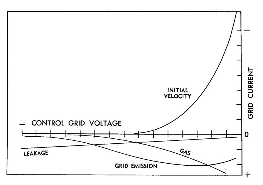
Figure 1. Sources of grid currents
Nonetheless it might be desired to add the “gas test” function to etracer as it might reveal some interesting behaviors of the DUT against different resistances in the grid bias circuit.
Figure 2 is a simplified circuit of the gas test circuit of a TV-7 excerpted from the TV-7 service manual. When the S110 switch is shorted the grid bias voltage is directly applied to the grid electrode of the DUT. When the S110 switch is open the grid bias voltage is connected to the grid electrode with a 180k resistor R128 in series. Assuming the polarity of the voltage across R128 is as depicted in figure 12 the actual voltage appears on the grid electrode is higher than the bias voltage when R128 is connected and hence the plate current should increase. By comparing the amount of plate current increase we can infer the impact of the grid current in the DUT at the specific operating point. On the TV-7 the pass criteria for the gas test is the increased plate current shall be within a certain percentage threshold.
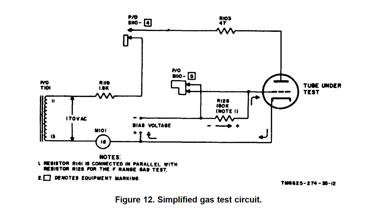
Figure 2 simplified gas test circuit in a TV-7 tube tester
The grid bias circuit in etracer
The grid bias circuit in etracer is depicted in figure 3.
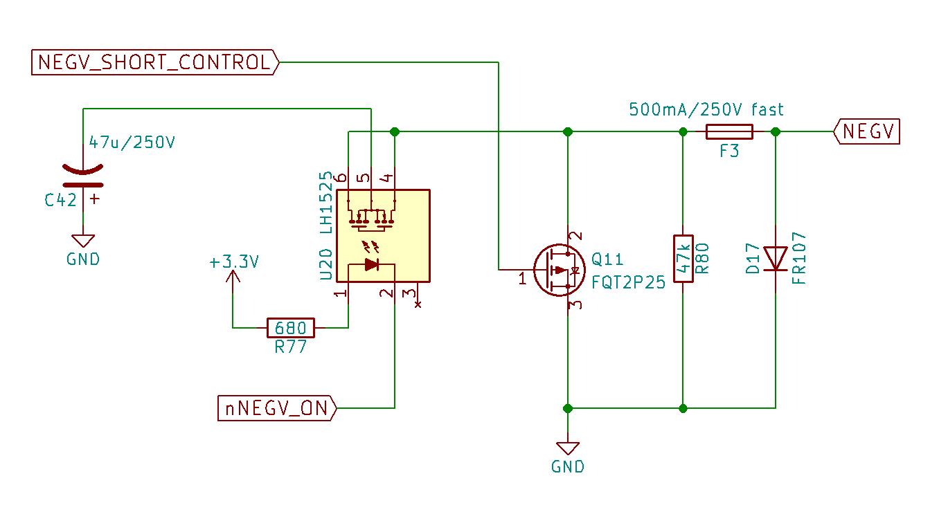
Figure 3. Negative supply circuit of etracer
The 47uF capacitor C42 is charged to the desired negative voltage. During a measurement pulse nNEGV_ON goes low to turn on the solid state relay U20 and C42 works as a battery connecting directly to the grid electrode of the DUT. The output resistance equals to the ESR of C42 which is very low (<1 ohm).
Modification to the etracer
The idea of implementing a gas test in etracer is very simple – just add a selector that chooses a series resistor to be connected between NEGV and the grid of DUT. Here we use an ON-OFF-ON DPDT switch to implement three different values of resistances: 0R (short), 1k ohms and 100k ohms. Other possible methods for supplying different resistance values include using a potentiometer or a multi-position rotary switch.
Note 1: The location of the resistance selector should be placed as close to the tubes sockets as possible.
Note 2: The 1k ohms resistor also acts as a grid stopper resistor to eliminate oscillations for some very high gm tubes.
Note 3: Please note NEGV can be as high (actually low as it is negative) as 200V. The voltage rating for the parts (selector, potentiometer, etc.) shall be carefully examined.
Note 4: etracer can test both sections of a twin-triode at once. When the output impedance for the negative supply is low it is safe to connect NEGV directly to the grid electrode of both sections. However, when the output impedance of the negative supply is high the two grid electrodes should be connected to a separate resistor otherwise the grid current on one section might interfere the grid bias on the other section. That’s why a DPDT switch in used instead of a SPDT switch. Figure 4 below depicts the connections for the components.
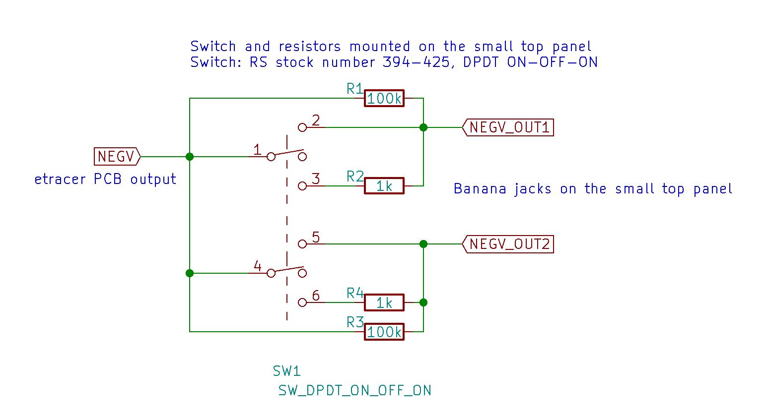
Figure 4. Connections for the switch and resistors
In figure 4 SW1 is a DPDT switch. The switch actually has three positions: on(1), off (2) and on (3). At position (1) pin 1-2 and pin 4-5 conduct. A short path is created between NEGV and both NEGV_OUT1 and NEGV_OUT2. This is also the original connection of etracer without the modification. At position (2) pin 1 and pin 4 connect to nothing and NEGV is connected to NEGV_OUT1 and NEGV_OUT2 through the two 100k resistors R1 and R3 respectively. At position (3) pin 1-3 and pin 4-6 conduct and thus R1 and R2 and R3 and R4 are connected in parallel respectively. Since 100k>>1k the resulting resistance is very close to 1k ohms. Hence NEGV is connected to NEGV_OUT1 and NEGV_OUT2 through two 1k resistors respectively.Figure 5 and figure 6 show the wiring in detail.
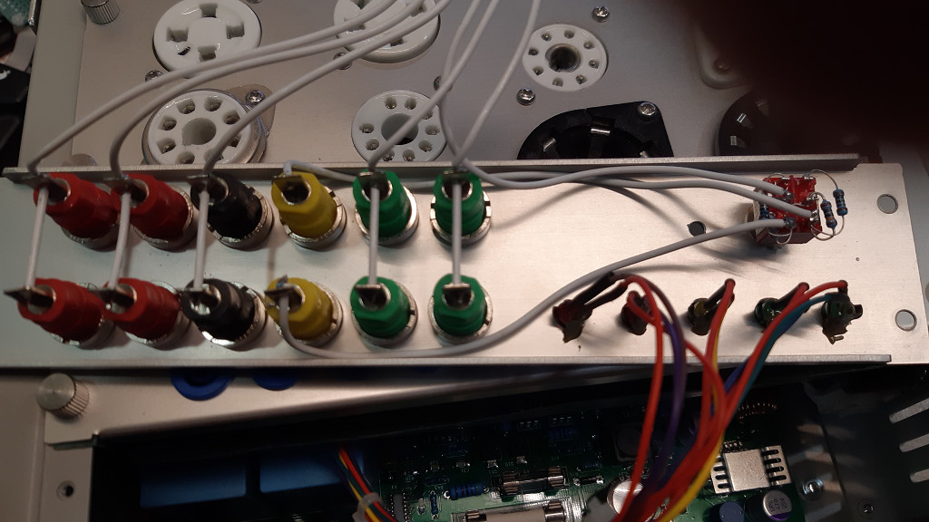
Figure 5. Wiring of the NEGV (yellow) posts.
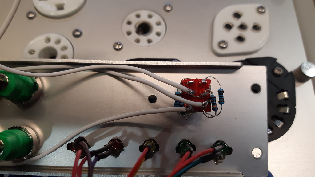
Figure 6. Wring of the resistors and switch.
Figure 7 shows the location of the toggle switch on the etracer panel.
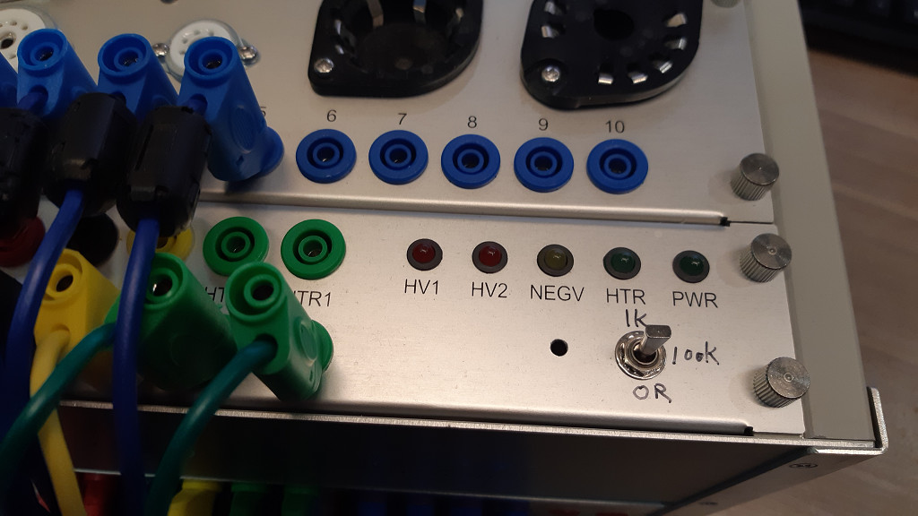
Figure 7. Recommended location for the toggle switch
Gas test procedure
A gas test procedure similar to TV-7 can be performed manually. Firstly put the switch at the short position and run a quick test and record the plate current. Secondly put the switch at the 100k position and run a quick test again. The difference in the plate current represents the gas test result. A pass-fail criterion can be designed at users discretion.
A step further
etracer can put the DUT at arbitrary bias condition. The user can pick different quiescent point and check the effect of the grid current at that specific operating point. Or a full-scan with different resistor settings will give the user a full picture of the behavior of the DUT with different resistances in the grid circuit.
References
[1] “Getting the most out of vacuum tubes”, Robert B. Tomer, 1960